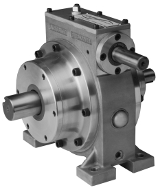
G-1600 25 HP Phase Drive
Downloads | Specifications | Operating Details | Benefits | Horsepower and Torque Ratings

The A. Fischer Phase-Drive offers a reliable, simple and precise unit that solves problems of phase adjustment, registration and timing quickly and efficiently. In addition, it also has the added inherent ability to be used as a speed reducer in 4:1 ratio.
Adjusting the timing of various power transmission components often requires costly downtime, because of the disassembly and re-positioning of shafts, gears, or chains, to bring about the proper phase position of one shaft with another.

Downloads
Specifications
| Lubrication | AGMA #4EP/ISO 150 gear oil is used in a positive splash system, integral sump, with an oil level sight glass for easy observation. Each Phase Drive is supplied with a breather vent and magnetic oil drain plug. |
| Shafts | Input and output shafts hardened and ground. One Piece adjustment shaft and worm is hardened and thread ground. Ground locknut threads. |
| Bearings | Input and output shafts have quality taper roller bearings. Planetary gears run on precision needle bearings. Adjustment shaft bearings of oil impregnated bronze. All shafts protected by oil seals. |
| Housing | #A356-T6 high strength and close grained impregnated aluminum alloy castings. |
| Gears | Hardened and precision ground on tooth form. |
| Gear Cage | Ductile iron and alloy steel. |
| H.P. Ratings | 25 H.P. |
| Weight | 51 lbs |
| Ratio | 4:1 |
| Warranty | 1 Year |
| Mounting Styles & Shaft Positions |
|
| Option | Handwheel |
Operating Details
| How it Works | Adjustment shaft, through worm-and-gear arrangement, rotates ring gear engaging three planetary gears in a housing connected to the output shaft, thereby advancing or retarding the output shaft position in relation to the input shaft. |
| Easy to Install | You can cut into any existing line shaft, couple the driving and driven shafts at either end, and you have instant adjustment of the rotational positions of the input and output shafts in relationship to each other. The unit can be used with a great variety of position sensing equipment, such as holding registration on printed stock during automatic cut-off operations. Typical applications include conveyor drives, printing rollers, dispensers, textile machinery, food processing, indexing heads, paper converting, feeders, cut-off machines, plastic web or film machinery, level winding equipment, packaging machines, speed correction, etc. |
| Manual or Electric Operation | Unlimited instantaneous adjustments in the input - output shaft relationships, through the entire 360°, are made simply by turning the adjustment shaft at the top of the unit. This may be done while running or stopped, manually by means of an available optional handwheel or connected at some distance by flexible shaft or universal joint arrangement. For automatic or remote operation, several motor packages are available. Input and output shafts revolve in either direction; both turn the same way and are the same diameter. The unit also functions as a 4:1 speed reducer. |
| Precision Built, Field Tested | A. Fischer Phase Drives are precision engineered and quality built throughout. All components are machined to exacting tolerances, utilizing CNC machining and turning centers to assure minimal variation and consistent interchangeability. A. Fischer Phase Drives include superior component parts like high quality taper roller bearings, precision needle bearings, hardened and tooth-form ground gearing. The quality and durability of A. Fischer Phase Drives has been proven in the field during the past 40 years. Many drives have been in constant operation, up to 24 hours a day/7 days a week with minimum attention through their operating life. We have designed and built A. Fischer Phase Drives so that they will surpass your engineering requirements and provide you with long lasting and dependable service. |
Benefits
- Leader and originator of phase drives
- Quality with remarkable performance for over 40 years
- On-the-fly instantaneous adjustment
- Quick and easy installation
- Rugged, precision-built construction
- Versatile with a wide range of applications
- Popular models in stock
- Various mounting styles and shaft positions
- Value-added customer modifications
- 1 year warranty
Horsepower and Torque Ratings
| INPUT | OUTPUT | ||||
| H.P. | R.P.M. | R.P.M. | Torque In-lb. | Maximum Overhung Load LB. | Maximum Thrust (In or Out) LB. |
| 42.3 | 3600 | 900 | 2962 | 534 | 201 |
| 41.2 | 3450 | 863 | 3009 | 541 | 204 |
| 37.3 | 3000 | 750 | 3134 | 564 | 212 |
| 32.0 | 2400 | 600 | 3361 | 603 | 227 |
| 23.0 | 1800 | 450 | 3641 | 658 | 248 |
| 25.0 | 1725 | 431 | 3656 | 667 | 251 |
| 19.8 | 1200 | 300 | 4160 | 743 | 280 |
| 19.0 | 1140 | 285 | 4202 | 755 | 289 |
| 17.3 | 1000 | 250 | 4361 | 785 | 296 |
| 14.3 | 750 | 188 | 4794 | 856 | 323 |
| 10.6 | 500 | 125 | 5345 | 966 | 364 |
| 6.7 | 250 | 63 | 6703 | 1187 | 447 |
| 3.5 | 100 | 25 | 8824 | 1566 | 590 |
Contact us for more information.
